Great Western locomotive sight feed lubricators and their relationship with smokebox luricator pipe covers
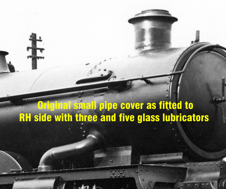
Lubricator pipe covers (often wrongly referred to as 'superheater covers') located over the joint between the smokebox and boiler.
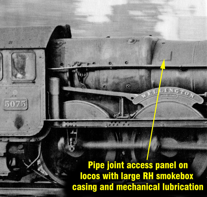
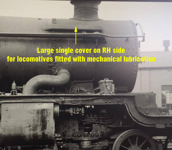
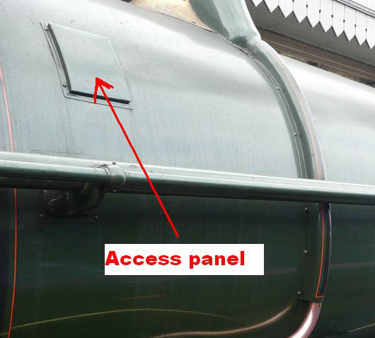
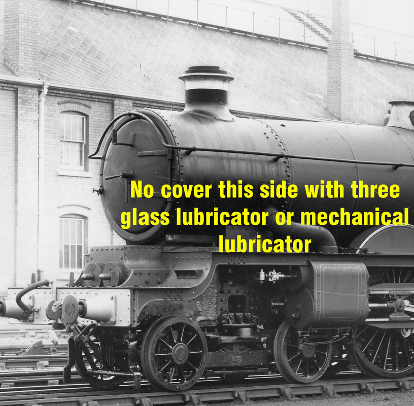
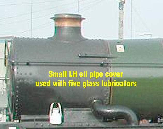
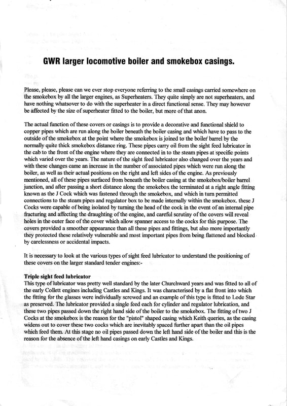
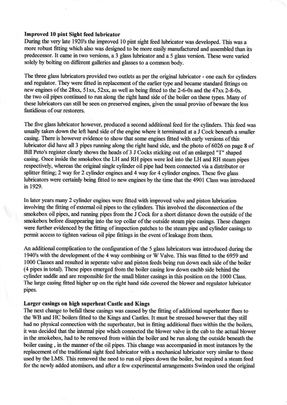
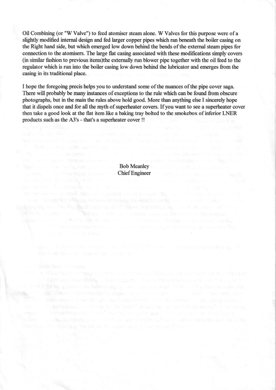
A lot of confusion surrounds the pressed metal covers or casings over the smokebox lubricator pipes where they emerge from under the boiler cladding and enter the smokebox itself. The drawings reproduced above go someway to explaining the variations.
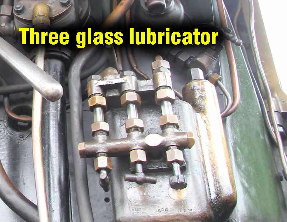
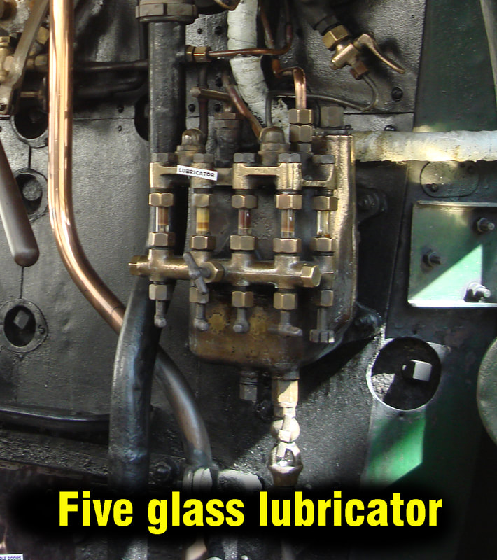
Basically the locomotives fitted with the original three glass hydrostatic lubricator fitted on the backhead, supply oil to the LH and RH cylinders via a splitter in the smokebox, together with an oil supply to the regulator valve. These locos have two oil pipes running under the cladding from the cab and emerge under a single pressed cover on the right hand side (driver's side) of the smokebox. Inside the smokebox the pipe for delivering oil to the cylinders divides into two via a splitter: one feed to the LH cylinder and the other to the RH cylinder. The second slightly smaller pipe feeds into the regulator valve. On four cylinder locos fitted with a three glass lubricator, the splitter divides the oil pipe into four feeds for lubrication to the two inside and two outside cylinders. Whether the locomotive has a superheater or not mainly bears no relationship to the outside visuals of the pipe cover, only to the piping arrangements within the smokebox. (See further article by Bob Meanley below)
When a locomotive was fitted with a five glass lubricator the cylinders on the RH and LH had their own separate oil feed pipes, the RH one running down the right hand side of the boiler together with the regulator valve oil pipe, the other running down the LH side entering the smokebox with a smaller, narrower casing covering the single pipe. The four cylinder locos fitted with the five glass lubricator had a similar arrangement.
When the larger locomotives were fitted with mechanical lubrication, only a large flat casing appeared on the RH side of the smokebox covering the oil and blower pipework, there was no cover on the LH side in this case. There was also a shallow square cover just forward of the firebox giving access to some pipe joints.
Having said all of that, you'll always find the odd loco photo that seems to defy the basic rules by acquiring for example an extra square or oblong panel somewhere on the boiler. This is invariably due to a pipe joint leak or split which has necessitated a quick fix by cutting a hole in the cladding to gain access, this is then plated or boxed over.
Here is a further interesting in-depth article by Bob Meanley of Tyseley fame on the subject covering the larger locomotives.
Basic Painting guide for Great Western locomotives
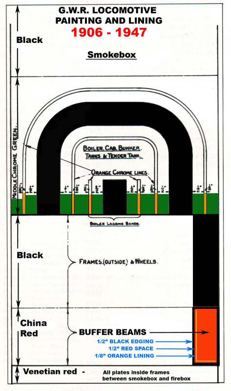
- This painting guide for Great Western locomotives has been sourced over the years from official records and specifications, together with further information and input from various professionals and organisations such as Alan Brackenborough and Tyseley locomotive works.
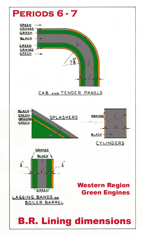
- This guide will start with the basic painting details from the end of the First World War and then develop and expand to cover lining, lettering and variations that have occurred over the years. Any input or comments will be most welcome to help build up the definitive GWR loco livery guide.
- Middle Chrome Green (Deep Bronze Green good available match) :
- Boiler and firebox cleating plates (up to rear edge of smokebox).
- Handrails and brackets. (Except on some locomotive vertical cab rails).
- Whistle shield.
- Fire-iron tunnel.
- Top feed clack covers either side of brass safety valve cover and pipework.
- Stand-alone clack-box covers.
- Dome covers.
- Safety valve casing (Except on engines having copper polished caps)
- Reverser housing.
- Cab sides, cab front, cab interior surfaces (including roof).
- Lower part of Nameplates between brass beading and splasher top)
- ATC box.
- Splasher fronts.
- Tender body sides and rear above footplate level.
- Tender and locomotive toolboxes (outside).
- Tank sides and fronts (Except Panniers with tanks finishing at the FRONT of the smokebox in which case the fronts are painted black).
- Tops of pannier and saddle tanks and fittings.
- Black:
- Smokebox, saddle and door.
- Outside steam pipe casings
- Ejector and pipe running down the right hand side of the boiler behind the handrail from firebox to smokebox.
- Reversing rod.
- Chimney, except for polished copper top.
- Inside of Safety valve.
- Cab roof (outside).
- Cab floor (apart from wooden floorboard areas which were kept natural)
- Shelf and front plate of bunker inside cab of tank engines.
- Firebox face inside cab (backhead)
- Splasher tops.
- Lamp irons.
- Insides of toolboxes.
- Ground of name and number plates around letters and figures.
- All horizontal footplate surfaces including narrow sections below cab.
- Hanging bars (valances).
- Drag boxes below cab and front of tender.
- All areas below footplate level.
- Cylinders and frames.
- Tender footplate including the narrow strip all around the main tank.
- Bead around top of tender sides and rear.
- All areas below footplate level including brake, draincock and sanding gear.
- Top surface and all inner areas of main tender tank (except toolboxes)
- Tender and bunker coal space and fittings.
- All areas of tender front.
- Coupling hooks.
- Buffer plungers.
- Red:
- (The 1947 spec reads: "Chinese red for buffer beams and buffer cases, Venetian red for all other areas listed below)
- Front locomotive buffer beam including buffer bodies.
- Rear tender buffer beam including buffer bodies.
- Vacuum pipe stands (within the area of the buffer beam on the tender).
- Inner faces of locomotive main frames, including stretchers, between firebox front and smokebox rear or rear face of inside cylinders.
- Crank axle.
- Eccentric straps and rods.
- Regulator handle (except for the grip area).
- Reverser screw handle (except for the grip areas).
- Lamps – pre 1937. (White phased in between 1936-38)
- Polished brass:
- Safety valve cover (bonnet) on engines with polished copper-cap chimneys.
- Cab side window frames.
- Spectacle plate (cab front) window frames.
- Brake valve, gauge glass frame, steam gauge bodies and blower valve.
- ATC bell.
- Whistles.
- Beading running down front of cab sides.
- Beading running down rear of cab sides.
- Beading around splashers.
- Oil boxes.
- Cylinder pressure relief valves.
- Draincocks.
- Name and number plate letters, numbers and surrounding frame beading.
- Polished copper:
- Top cap area of chimney.
- Pipe work inside cab on backhead except for large brake valve pipe (black) and steam heat control pipe (off white lagging).
- Draincock pipes.
- Oil feed pipes.
- Bright Steel:
- All motion parts, including slide bars, valve gear, coupling rods, connecting rods and inside motion.
- Vertical rear Cab handrails.
- Vertical front tender handrails.
- Buffers and shanks on prestigious locomotives.
- Grip areas of regulator and reversing handles in cab.
- Smokebox door handles.
- Centre quadrant slot area of reversing rod.
